A more complex shape
Instead of drawing a triangle, we are now going to draw a more complex shape: a teapot. The Utah teapot is a famous 3D model that is often considered as one of the "hello world"s of graphics programming.
In a real application, complex models (by "complex" I mean anything more than a few vertices) are loaded from files at runtime. But for the purpose of this tutorial, we are going to use a Rust file that contains the already-parsed model instead. You can find it here.
This file provides three arrays:
- An array of vertex positions (called
VERTICES). - An array containing the normals (
NORMALS) of each vertex. The normal of a vertex is the vertex perpendicular to the object's shape at this point. We are going to load this data but use it only in the following tutorials. - An array containing the indices (
INDICES).
All shapes in graphics programming are made of triangles. In a real 3D model multiple triangles often use the same vertex, therefore to avoid duplicating vertices we store the list of triangles and list of vertices separately.
Each element of INDICES is in fact an index in the VERTICES and NORMALS arrays, and each
group of three indices forms a triangle. For example the first three elements of INDICES are
7, 6 and 1. This declares a triangle that will connect the vertex 7, 6 and 1 whose data is
in VERTICES and NORMALS.
Loading the shape
We are going to use the Rust file containing the model as a module named teapot.
# #![allow(unused_variables)]
#fn main() {
mod teapot;
#}
Loading the data is then very straight-forward:
# #![allow(unused_variables)]
#fn main() {
let positions = glium::VertexBuffer::new(&display, &teapot::VERTICES).unwrap();
let normals = glium::VertexBuffer::new(&display, &teapot::NORMALS).unwrap();
let indices = glium::IndexBuffer::new(&display, glium::index::PrimitiveType::TrianglesList,
                                      &teapot::INDICES).unwrap();
#}
We have a new type here: the IndexBuffer. As you can tell from its name, it is a buffer whose
purpose is to stores indices.
When we create it, we have to indicate the kind of primitives that are inside the buffer, here a
list of triangles. There are several kind of primitives but the triangles list is the
most common.
The program
We need to make a few changes to the vertex shader.
Instead of just one, we are going to get two attributes now: position and normal.
Also, position is now a vec3 instead of a vec2.
#version 140

in vec3 position;
in vec3 normal;

uniform mat4 matrix;

void main() {
    gl_Position = matrix * vec4(position, 1.0);
}
The value that we set to the gl_Position variable is the position of the vertex in window
coordinates. Why does it have four components? Here is the answer:
- The window coordinates space is in fact in 3D! OpenGL treats our screen as three-dimensional.
- The first three coordinates are divided by the fourth coordinate immediately after our vertex shader is executed. The fourth coordinate is then discarded.
For example if we output gl_Position = vec4(2.0, -4.0, 6.0, 2.0);, the GPU will divide the
first three coordinates by 2.0 and obtain (1.0, -2.0, 3.0), which are the screen coordinates.
The first two coordinates (1.0 and -2.0) then represent the position of the vertex on the
screen, and the third (3.0) represents the depth of the vertex. This depth value is for the
moment discarded, but we will use it in a later tutorial.
As for the fragment shader, let's just output the color red for the moment:
#version 140

out vec4 color;

void main() {
    color = vec4(1.0, 0.0, 0.0, 1.0);
}
Drawing
Compared to the previous sections, there are two differences when drawing:
- We have two vertex buffers. This is solved by passing a tuple of the buffers. The first
parameter of the
drawfunction must implement theMultiVerticesSourcetrait, which includes single buffers and tuples of buffers. - We have indices, therefore we pass a reference to our index buffer to the
drawfunction.
# #![allow(unused_variables)]
#fn main() {
let matrix = [
    [1.0, 0.0, 0.0, 0.0],
    [0.0, 1.0, 0.0, 0.0],
    [0.0, 0.0, 1.0, 0.0],
    [0.0, 0.0, 0.0, 1.0f32]
];

target.draw((&positions, &normals), &indices, &program, &uniform! { matrix: matrix },
            &Default::default()).unwrap();
#}
And if you execute this code, you will see...

...wait, something's wrong!
It is very common in graphics programming to have problems like this, where you don't always understand what is going on. Try to guess what the problem is here!
The answer here is that the model is too large to fit in the screen. The coordinates of
the model range between approximately -100 and +100, but the logical coordinates of our screen
range between -1.0 and 1.0. To fix this, let's adjust our matrix to rescale the model to
1/100th of its size:
# #![allow(unused_variables)]
#fn main() {
let matrix = [
    [0.01, 0.0, 0.0, 0.0],
    [0.0, 0.01, 0.0, 0.0],
    [0.0, 0.0, 0.01, 0.0],
    [0.0, 0.0, 0.0, 1.0f32]
];
#}
And you should now get the correct result:
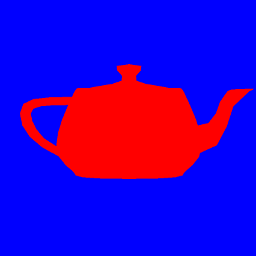
This looks very primitive, but it is a good first step towards 3D rendering.